Mitsubishi Y03 amplifier not installed: site record of an MDS-D-V2-160160 with no display
Retain the original MDS-D-V2-160160 no-display/Y03 record and photographs, with checks of connection, supply and axis correspondence. Live cable removal is explicitly excluded as a troubleshooting step.
Contents
The original site record concerns Mitsubishi CNC alarm Y03, “Amplifier not installed,” with one MDS-D-V2-160160 drive showing no display. It includes two photographs but no measured supply values, complete repair procedure or restart results. It is therefore retained as a symptom record without adding a conclusion that the equipment was repaired.
What Y03 establishes
Page 48 of M800/M80/E80/C80 handbook IB-1501280-B explains Y03 as a drive unit not correctly connected, with checks covering connections, cables, input power and axis-number settings. This does not establish that the drive itself has failed. The exact system version in this case must still be checked against its own documentation; an M70 must not adopt M80 parameters merely because the message is the same.
Match the module without a display to its axis
Record the complete NC alarm, axis name, exact model and display state of each drive. Distinguish no display on every module from no display on only one. Mark unclear details in existing photographs as unconfirmed rather than inferring them from adjacent modules. Record the time and actual actions if modules were recently replaced, parameters restored or cables moved.
Check connections and supply safely
Site personnel can first organize externally visible information. Measurements inside the cabinet, cable disconnection and module inspection require electrical repair personnel to isolate power and confirm stored energy has dissipated under the machine's procedures. Do not unplug or plug encoder or communication cables while energized, or look directly into optical-fibre ports to judge communication.
Cross-check equipment drawings, actual axis connections and existing parameter backups. Before the cause is understood, do not arbitrarily change axis numbers or remove an axis configuration to clear the alarm. No display is an investigation clue, not a substitute for checking input conditions and module state.
Preserve unresolved items at handover
This case still lacks a definite final fault location and restart-validation record. Later measurements and repair work orders should be added to the same incident, not assembled from a similar machine's repair to create a result for this one. See the complete alarm screenshot checklist for evidence collection and the existing Y03-related record (Chinese) for other Y03 site material.
Original site photographs
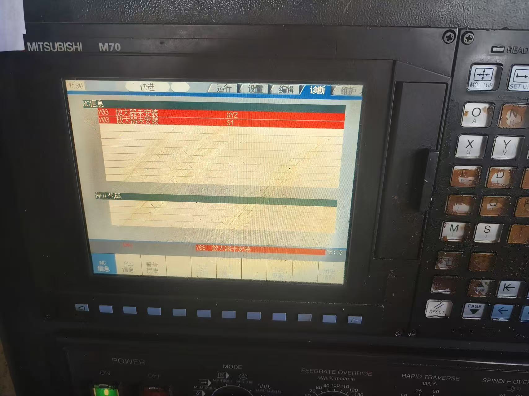
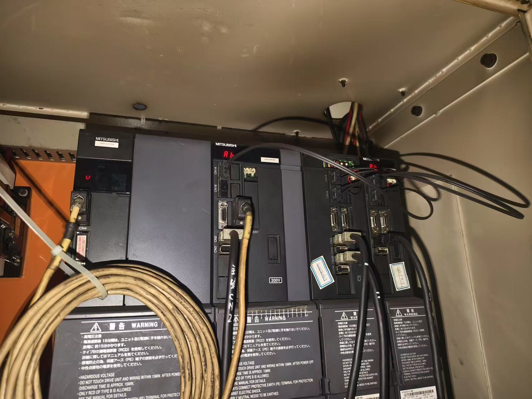
Reference: M800/M80/E80/C80 Series HANDBOOK, IB-1501280-B, §3.1, printed page 29; power-supply alarm table on page 39; MCP alarms on page 48. This text explains scope and suggests ways to organize site records. Follow the documentation for the actual system and machine builder for specific operations.